


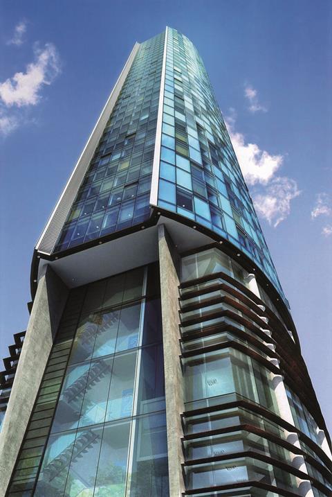
As lightweight structures, curtain walls must be carefully designed to maximise acoustic performance. This module, sponsored by Siderise, explains how acoustics should be incorporated into the design process

How to take this module
UBM’s CPD distance-learning programme is open to anyone seeking to develop their knowledge and skills. Each module also offers members of professional institutions an opportunity to earn between 30 and 90 minutes of credits towards their annual CPD requirement.
This article is accredited by the CPD Certification Service. To earn CPD credits, read the article and then click the link below to complete your details and answer the questions. You will receive your results instantly, and if all the questions are correctly answered, you will be able to download your CPD certificate straight away.
CPD CREDITS: 60 MINUTES
DEADLINE: 8 DECEMBER 2017


INTRODUCTION
For facade engineers, a curtain wall is an efficient non-structural element used to weatherproof a building. But from a noise point of view, a curtain wall is a lightweight structure, and lightweight structures do not go hand in hand with good acoustic performance.
As far as acoustics are concerned, the aims of any development fall into two categories. The first is the perception of the acoustics of the completed development by its occupiers and visitors. The second is the control of the acoustic impact on the surroundings – internal and external – so that the development can operate without fear of a noise nuisance action being brought. In delivering both, the designer must satisfy legislative requirements as well as those of the client or end user.
This CPD will explain how acoustics should be incorporated into the design process for curtain-walled buildings to ensure that these aims are achieved. While it covers a specific application, similar mechanisms and considerations can be applied in most areas of the built environment when considering room-to-room acoustics.
SOUND TRANSMISSION
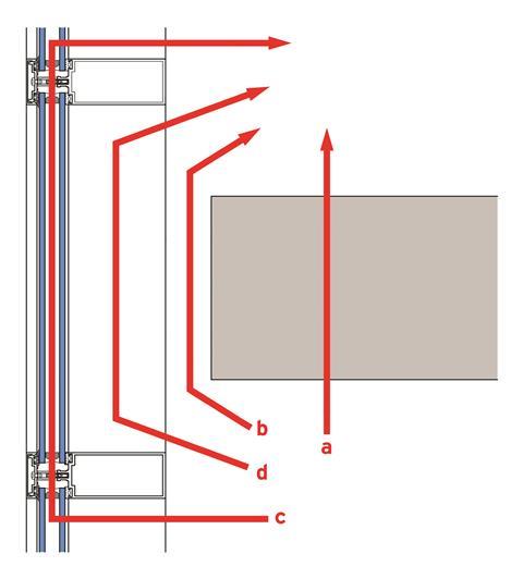
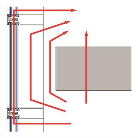
Figure 1 shows the four paths by which sound may be transmitted from floor to floor:
a. Direct sound transmission path
b. Flanking sound transmission path via closure/movement detail
c. Flanking sound transmission path via facade glazing/structural elements (mullions and transoms)
d. Flanking sound transmission path via hollow of the mullion
The overall performance is potentially controlled by all the path components shown above.
A curtain wall is designed to resist air and water infiltration, wind forces, seismic forces, and its own dead load. Modern curtain wall systems can accommodate large amounts of movement without glass breakage or water leakage. This is achieved by maintaining a movement joint between the curtain wall facade and the structure of the building. The movement joint is effectively a gap or cavity between the slab edge and the rear of the facade, which needs to be effectively sealed to maintain the acoustic integrity of the building.
The seal would normally be expected to satisfy the following criteria:
- High levels of acoustic performance
- Fire rating to maintain compartmentation (both insulation and integrity)
- Able to expand and contract with the cyclic movement of the facade
- Flexible to prevent continual direct mechanical linkage
- Provide an airtight seal
- Resistant to moisture/water.
Room-to-room sound performance is effectively determined by the weakest link. This means that very careful consideration should be given to any potential weak point to ensure it does not become the limiting factor in the overall sound transmission performance. The movement joint, together with mullions and transoms, should be thoroughly assessed.
It is common for the seal specification to be based only on compliance with the relevant fire regulations. However, it is important to consider the acoustic implications in parallel, as well as the performance of the closure arrangement.
Ideally, the cavity seal should be selected at the design stage. At this point, the greatest range of suitable products are available to the designer, and they can be selected based on factors such as cost-effectiveness, ease of installation, acoustic performance, etc. Post or remedial treatment severely limits the products available. It is also invariably more expensive, less practical to install and may not always be fully compliant.
If the cavity seal is only considered following any form of on-site acoustic test, this would indicate that a non-compliant seal was initially selected at design stage. The cost of any corrective treatment is obviously additional to the initial installation. Such extra costs can be substantial due to limited product availability and restricted accessibility. Also, penalties may be incurred due to delays to following trades and possibly a late handover to the client.
The very worst scenario is to only consider the seal when the client has already occupied the building. Shortcomings in sound performance identified at this point indicate a basic failure to meet the project’s acoustic design criteria. Remedial treatment is disruptive, unsightly, very expensive and potentially less effective, possibly even requiring that the client compromise on performance.
RELEVANT LEGISLATION AND STANDARDS
Residential
Residential acoustics is covered by Building Regulations Approved Document E, which applies to all new residential buildings in England and Wales. This requires that a property is either registered and built using standardised Robust Details, using only approved products, or constructed using alternative techniques and materials. In the latter case, compliance is confirmed through pre-completion testing (PCT), where a sample number of dwellings are tested by a UKAS or ANC-accredited noise consultant. There are no Robust Details for curtain wall residential properties, therefore all curtain wall buildings must demonstrate compliance by means of PCT.
Education
Building Bulletin 93 (BB93) contains the Building Regulations for all schools in England and Wales. While schools in Scotland, sixth-form buildings, higher education colleges and universities in the UK are not covered, most are still designed to meet the BB93 standards. Separation performance values vary significantly depending on the type of adjoining rooms (eg, classrooms, library, music rooms). For example, a floor separating two general classrooms would require a lower performance than that between a music room and library.
Offices
There are no acoustic building regulations applying to office spaces. Performance criteria are generally selected by the project noise consultant based on the requirements of the client or occupier. Recommendations from the British Council for Offices (BCO) and the World Health Organisation (WHO) may also influence this decision process depending on the proposed or possible use of the space.
Industrial units
There are no regulatory acoustic requirements applicable to industrial units. Performance values are generally selected by the project noise consultant based on the individual requirements of the client or occupier. The performance of the building envelope may be affected by local council limits for background noise levels. The Control of Noise at Work Regulations (Noise Regulations) and WHO recommendations may also influence the final performance criteria.
ACHIEVING COMPLIANCE
When considering the vertical (floor-to-floor) transmission of airborne sound energy, the applicable criteria (regulatory or otherwise), will usually be in one of the following forms:
- dB DnTw – a final site measured value
- dB Rw – a laboratory-tested value for direct sound transmission of a component(s)
- dB Dnfw – a laboratory-tested value for flanking sound transmission of a facade system
- dB DnT(mf),w – a final site measured value and relates to education buildings.
Where the abbreviations as defined as follows:
- dB = decibel
- D = difference
- n = normalised
- T = reverberation time
- R = reduction
- f = flanking
- mf = mid frequencies
- w = frequency weighted.
It is essential to understand the significant differences between these terms in order to validate or otherwise prove potential compliance. In general, site-measured values cannot match those recorded in a sound laboratory. The difference will vary depending on the method of test and actual performance levels, but a guide 5dB minimum practical difference is commonly quoted.
Further comparative variations may arise from fundamental differences in the nature of the tests, as well as how results are then finally expressed – for example, some are adjusted to a 10m2 reference area. By way of example, to achieve a 45dB DnTw, the floor slab would normally need to offer a minimum Rw performance of 50dB and the facade 50+dB Dnfw.
Many fire seal products claim to be compliant with common fire standards. Other important characteristics and properties of the seal should also be considered when undertaking product selection:
- sound transmission performance
- ability to expand and contract with the facade’s cyclic movement
- proven fire performance (both integrity and insulation) when abutting
- deforming structures when abutting
- provision of an effective smoke seal
- resistance to moisture/water
- ability to provide a flexible closure limiting possible flanking transmission.
When considering the sound transmission characteristics it is essential that accurate test data is available for the seal itself and common combined closure arrangements. Without this information, validation of performance compliance is impossible.
ACOUSTIC ASSESSMENT
The movement joint seal between the floor slab edge and the rear of the facade can be viewed and assessed for acoustic performance in two quite different ways.
It may be considered to be an inclusive component of total facade flanking transmission. This approach requires testing for each known facade variant with a range of typical project cavity widths. This is necessary because the width of the seal directly affects its acoustic significance. Alternatively, it may be considered as a simple extension of the floor slab. This method, with reference to known Rw data for both the floor slab and the closure detail, permits the calculation of an overall floor value. This is achieved by means of a simple composite SRI calculation.
A curtain wall facade should always be tested in a UKAS-accredited laboratory. The acoustic data obtained will usually be in the form of a Dnfw value. The project noise consultant will require copies of the test certificates for the exact – or at least very close – constructions to confirm compliance.
Floor slabs should also always be tested in a UKAS-accredited laboratory. The acoustic data
will normally be in the form of an Rw value. Alternatively, the project noise consultant may have access to library test performance data for the particular floor construction employed.
When validating performance by the “extension to floor slab” method, the following information is required for the composite SRI calculation:
- Relevant performance criteria in dB and form (eg, Rw, Dnfw, DnTw, etc)
- Typical room depth and cavity width
- Floor construction, particularly slab thickness
- Any reliable additional path elements (eg, raised access floors, dwarf walls, high mass bulkheads).
The following general rules apply when considering the minimum required SRI performance of the fire seal closure arrangement:
- The larger the cavity width and/or the thinner the slab, the higher the seal’s required SRI performance
- The smaller the cavity and/or thicker the slab, the lower the seal’s required SRI performance.
Gaps and poor fit
Overall acoustic performance can be significantly degraded due to gaps or a poor fit arising from inadequate workmanship or unusual or complex detailing. Careful attention should be paid to ensure a continuous seal for both the fire seal and/or any applied acoustic upgrades.
Additional sound path elements
When calculating the seal’s minimum performance requirements it is prudent to ignore the possible contribution from other intervening elements such as suspended ceilings. Their performance cannot always be relied upon, due to either a local absence or degradation arising from elements such as light fittings or ventilation. It should instead be considered as an added safety factor for final compliance.

SRI PERFORMANCE VARIATIONS
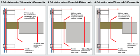
Figures 2-4 (above) demonstrate typical variations in the required minimum SRI performance of the fire seal. All three are calculated based on a room depth of 4m, a performance criteria of 45dB DnTw (or alternatively 50dB Dnfw for the facade). They assume that the general flanking performance offered by the facade construction is adequate to meet the overall performance criteria. The required minimum performance variations for the seal arise only due to the changes to the slab and cavity dimensions shown. The curtain wall bracket is omitted from drawings for clarity.
In these three examples, the cavity fire seal closure was likely to represent the performance limiting factor given the required minimum SRI values indicated. However, by the application of specialist high-mass acoustic upgrades to the fire seal, it is possible to substantially improve the closure performance.
CLOSURE PERFORMANCE VARIATIONS
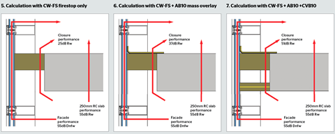
The examples below show possible variations in closure performance based on adding various upgrades and their effect in terms of the maximum achievable overall DnTw values. All three examples are calculated based on a room depth of 4m, a 250mm-thick reinforced concrete slab, a 200mm cavity width and a facade offering a 55dB Dnfw flanking transmission performance.
Figure 5 uses a SIDERISE CW/FS120 fire stop alone (tested 25dB Rw performance). The maximum overall performance achievable is calculated at 33dB DnTw.
Figure 6 uses the SIDERISE fire stop together with an applied SIDERISE AB10 flexible overlay (tested 37dB Rw performance). The maximum overall performance achievable is calculated at 44dB DnTw.
Figure 7 is as Figure 6 above but additionally includes a SIDERISE CVB/C10 high mass slab below (tested 51dB Rw performance). The maximum overall performance achievable is calculated at 49.7dB DnTw. This represents a drop of only 0.3dB from the maximum performance achievable from this construction which is calculated at 50dB DnTw using standard assumptions.
FLANKING TRANSMISSION
Flanking transmission is used to describe any non-direct path of sound transfer. Total flanking transmission comprises a number of potential individual transfer mechanisms. One of the most important is generally referred to as structure-borne sound transmission. When sound impinges on a facade’s face, this physically excites the facade inducing bending waves. This energy is transferred to any adjacent areas where it is re-radiated from the facade’s internal surfaces.
Many factors potentially influence structure-borne transmission in a curtain wall facade. These include stiffness, surface mass, span distances and discontinuity. Most of these characteristics are fundamental to the individual system selected. In consequence, most major manufacturers can advise probable Dnfw values for various glass weights, mullion/transom sizes, framing centres, etc.
This value effectively provides a basic performance assumption for the paths (c) and (d). However, due to minor design differences, it may be prudent to effectively eliminate path (d) as a potential performance limiting mechanism.
How to take this module
UBM’s CPD distance-learning programme is open to anyone seeking to develop their knowledge and skills. Each module also offers members of professional institutions an opportunity to earn between 30 and 90 minutes of credits towards their annual CPD requirement.
This article is accredited by the CPD Certification Service. To earn CPD credits, read the article and then click the link below to complete your details and answer the questions. You will receive your results instantly, and if all the questions are correctly answered, you will be able to download your CPD certificate straight away.
CPD CREDITS: 60 MINUTES
DEADLINE: 8 DECEMBER 2017
Privacy policy
Information you supply to UBM Information Ltd may be used for publication and also to provide you with information about our products or services in the form of direct marketing by email, telephone, fax or post. Information may also be made available to third parties. UBM Information Ltd may send updates about Building CPD and other relevant UBM products and services. By providing your email address you consent to being contacted by email by UBM Information Ltd or other third parties. If at any time you no longer wish to receive anything from UBM Information Ltd or to have your data made available to third parties, contact the Data Protection Coordinator, UBM Information Ltd, FREEPOST LON 15637, Tonbridge, TN9 1BR, Freephone 0800 279 0357 or email ubmidpa@ubm.com. View our full privacy policy at www.building.co.uk/cpd


No comments yet