


This module explores the use of solar photovoltaic technology to create on-site renewable energy. It is sponsored by Kalzip
Click here to take the CPD module.
How to use this module: BD Reviews’ free continuing professional development distance learning programme is open to everyone who wants to develop and improve their professional knowledge and skills. These modules can contribute to your annual programme of CPD activity to help you maintain membership of professional institutions and bodies. All you have to do is read this module then take the questions via the link above or at the bottom of the page.
Module 12 deadline: December 16 2011
There are many reasons why governments, developers and building owners are becoming increasingly interested in renewable forms of energy.
The drivers for renewable energy include:
Rising energy prices: Renewable technologies such as solar photovoltaics (PV) can help to mitigate the volatility of oil prices of recent years.
Climate change: It is widely accepted that reducing greenhouse gas emissions from the burning of fossil fuels is a matter of international priority. There seems to be growing evidence of more severe weather events caused by global warming, all of which have a severe economic and social impact.
Compliance with EU law: The Energy Performance of Buildings Directive, which became law in 2006, requires member states to consider renewable sources of energy in the design of all buildings with a useful floor area of 1000sq m or above.
Local planning strategy: The benchmark target for renewables is set at 10% of the building’s energy consumption requirements, as in the Merton Rule pioneered by Merton council in south London.
This states that in public and commercial developments of over 1,000sq m or in residential developments of 10 dwellings or more, 10% of the project’s energy requirements should be provided by on-site renewable sources, where economically and technically feasible. This rule has now been adopted by more than 40 local authorities in the UK.
Introduction to PV technology
PV technology is a renewable energy technology that converts the sun’s radiation into electrical power. Since its discovery in the US in the 1950s, PV has been used in a number of applications, such as providing power for remote telephones and temporary military facilities, as well as large-scale land-based solar plants, usually in hot, arid climates.
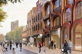
When used on the roofs of buildings, PV technology provides an additional income stream for the building owner and clean electricity for the occupants.
Roofing applications
- Roof-mounted panels: Retrofitting PV by bolting panels to an existing metal roof.
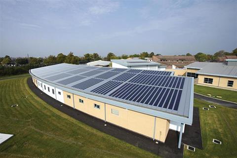
- Integrated solar metal roofing: Laminated solar metal roofing is completely integrated with the roof covering, as with Kalzip’s AluPlusSolar.
- Overcladding PV laminates are bonded to fabricated aluminium panels. The panels can be bolted to an existing standing seam roof and angled to the optimum pitch to maximise their solar annual yield, as with Kalzip’s SolarClad.
Two main types of PVs used in roofing products
- Crystalline cells
Crystalline silicon is produced in an energy-intensive process where cells are cut from melted and recrystallised silicon. The cells have a marble-like appearance and are normally bound into a panel with a glass top and an aluminium frame. This type of PV panel is usually fixed to a roof or facade or mounted on the ground in solar farm developments.
- Amorphous silicon:
Amorphous silicon cells take the form of a flexible 4mm-thick PV laminate. An ethylene tetrafluoroethylene (ETFE) weatherproof coating makes the laminate both flexible and durable. For these reasons, the PV laminate can be bonded to an aluminium standing seam roof cladding. PV laminate technology has a lower embodied energy than crystalline cells because the manufacturing process used to make amorphous silicon products is not as energy intensive.
Amorphous silicon also absorbs light more effectively than crystalline, so the cells can be thinner, and so require less material to be used in supporting structures.
The triple-junction cell consists of three separate layers of amorphous silicon optimised for the red, green and blue portions of the light spectrum. The thickness of the complete triple-junction cell is less than 1 micron and is bonded to a flexible stainless-steel substrate.
This is the technology used in Kalzip’s integrated solar metal roofing systems. The spectrum-splitting triple junction amorphous silicon technology makes the cell more efficient in overcast conditions and gives a higher overall annual yield in northern European climates than crystalline modules.
In an integrated solar metal roofing system, each laminate cell is fitted with bypass diodes. This means that if, for example, a bird perches on one cell, the others remain operational.
The manufacturer of the PV laminate also provides a performance warranty that guarantees the electrical output to be at least 92% of the nominal rated power after 10 years, 84% after 20 years and 80% after 25 years.
Design considerations for integrated solar metal roofing projects
There are a number of design considerations to take into account when planning an integrated solar metal roofing project:
- The allowable roof pitch is between 3° and 60°.
- Standing seam panels can be mechanically smooth-curved to a minimum radius of 15m.
- Different combinations of PV laminates can be bonded to aluminium roof sheets up to a length of 25m.
- The minimum system size is 2kWp (kilowatt peak). This equates to 14 136W modules with a gross roof area of about 50sq m.
- High-density insulationis recommended for roof walkability.
Operation of triple-junction silicon cells
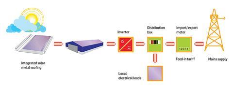
During daylight hours the triple-junction silicon cells, encapsulated within the PV laminate, convert the sun’s energy into a direct current (DC). This electricity is fed from the roof into one or a number of inverters that convert the DC into an alternating current, which can then be used to power electrical appliances.
The building’s distribution system monitors local demand for electricity, and the clean solar energy is used within the building first.
If demand is high, electricity from the grid is imported to top this up. If the demand is low or zero, surplus electricity is exported to the grid and the owner (or whoever pays the bills) is credited per kilowatt hour (kWh) under the government’s Feed-in Tariff scheme. More information about the tariff can be found at www.carbontrust.co.uk
Using solar design software
There are many commercially available design applications for PCs, which can aid in the design of solar power systems and carbon emissions calculations. They all operate using similar mathematical algorithms and the basic principle is fairly straightforward. One example is Kalzip SolarDesigner, developed by Valentin Software, which can be downloaded at www.kalzip.com
Climate data
The first step is to select a climate data file based on historical averages of meteorological data recorded at various weather stations around the UK that give the total annual solar irradiation received on a horizontal plane on the Earth’s surface. This irradiation becomes generally weaker moving north, ranging from over 1,100 kWh/m2 in the Channel Islands to just under 800 kWh/m2 in the Shetland Islands.
PV module selection
The next step is to select the type of module and the solar power system size. The orientation and pitch of the roof must also be specified. Note that the sign convention in solar design is to measure clockwise angles positively from 0° (due south) to 180° (due north), and anti-clockwise angles negatively, so due west is +90° and due east is -90°.
The scale ranges from 100% for south-facing panels oriented at 40° pitch to around 60% for an east- or west-facing vertical facade.
Project report
The application then produces a project report, which can be printed to PDF and sent to the customer. This gives an over-view of the system size, the type of module selected, roof pitch and orientation, and the peak power output based on the selected climate data file. It also gives the annual electrical yield from the PV generator array, which is expressed in kilowatt hours per annum (kWh/a).
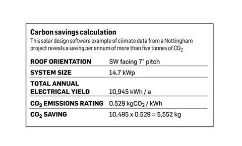
Carbon savings calculation
Carbon dioxide emissions ratings for various sources of energy are given in SAP 2009 (March 2010), which is cited in Part L2 of the Building Regulations for England and Wales. This gives the emissions ratings for various sources of energy. Grid-displaced electricity, such as that generated by PV systems, has a value of 0.529kgCO2/kWh. In order to calculate the reduction in carbon emissions, simply multiply the total annual yield from the PV generator array by the emissions rating value.
Postscript
To complete this CPD, read the module and click here to take the test online. If you experience any problems viewing the test online, contact bdreviews.cpd@ubm.com
MODULE 12 DEADLINE: December 16 2011
Privacy policy:
Information you supply to UBM Information Ltd may be used for publication and also to provide you with information about our products or services in the form of direct marketing by email, telephone, fax or post. Information may also be made available to third parties.
“UBM PLC” may send updates about BD CPD and other relevant UBM products and services. By providing your email address you consent to being contacted by email by “UBM Information Ltd” or other third parties.
If at any time you no longer wish to receive anything from UBM PLC or to have your data made available to third parties, please write to the Data Protection Coordinator, UBM PLC, FREEPOST LON 15637, Tonbridge, TN9 1BR, Freephone 0800 279 0357 or email ubmidpa@ubm.com
Sponsor
For more information, go to www.kalzip.com


No comments yet