







Sponsored by PolyFoam XPS, this CPD module explores the principles behind using extruded polystyrene (XPS) insulation in masonry cavity walls below damp-proof course (DPC) level, examining relevant Building Regulations guidance, detailing approaches and the role of thermal modelling in achieving robust building performance
Deadline for completion Friday 20 November 2026
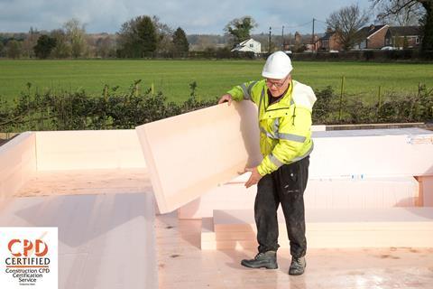
Controlling moisture at the base of a building is a fundamental requirement of durable construction. Nowhere is this more critical than at the junction between the ground floor and the external wall, where structural elements, damp protection and thermal performance must all be carefully co-ordinated. This interface – typically located below damp-proof course (DPC) level – is exposed to persistent ground moisture and, if poorly detailed, can become a point of failure for both fabric performance and occupant health.
In recent years, there has been growing interest in the use of extruded polystyrene (XPS) insulation within masonry cavity walls below DPC level. This interest is often driven by projects seeking to maintain continuity with insulation strategies used above DPC level, while introducing a material that can better withstand the moisture conditions present below ground. Unlike many conventional insulation materials, XPS is characterised by low water absorption and high compressive strength, making it suitable for applications where exposure to moisture is unavoidable.
The regulatory framework governing moisture resistance in England and Wales is set out in Approved Document C of the Building Regulations, which addresses the protection of buildings from ground moisture and the provision of damp-proof courses and damp-proof membranes (DPMs). The design of floors is closely linked to wall construction below DPC level, as the positioning of insulation and DPMs within the floor build-up directly influences junction detailing.
Alongside moisture control, thermal performance must also be considered. Junctions between floors and external walls are a known source of thermal bridging, which can reduce overall energy efficiency and increase the risk of surface condensation and mould growth. Building Regulations therefore require designers to consider the linear thermal transmittance – commonly referred to as the psi (ψ)-value – of these junctions as part of a compliant fabric strategy.
The suitability of insulation materials for use in masonry cavity walls is typically demonstrated through independent third-party assessment and certification. However, insulation products used below DPC level do not always carry certification for this specific application, requiring designers to rely on a combination of regulatory guidance, material properties and technical justification.
This module examines the use of XPS insulation in masonry cavity walls below DPC level, beginning with a detailed review of moisture resistance requirements under current Building Regulations. It then explores how the material characteristics of XPS can be applied to this context, supported by thermally modelled scenarios that assess junction performance. The aim is to provide specifiers with a clear, evidence-based understanding of how below-DPC detailing can be approached to achieve both moisture resilience and robust thermal performance.
Regulating moisture at ground level
The control of moisture in buildings is governed in England by Part C of Schedule 1 to the Building Regulations, which addresses site preparation and resistance to contaminants and moisture. Within this, Requirement C2 – Resistance to moisture – sets out the overarching performance standard that must be achieved by the building fabric.
Requirement C2 states that floors, walls and roofs must adequately protect both the building and its occupants from the harmful effects of moisture arising from:
- Ground moisture
- Precipitation, including wind-driven rain
- Interstitial and surface condensation
- Water associated with sanitary fittings or fixed appliances.
In the context of below-DPC detailing, the primary considerations are ground moisture and condensation risk, with precipitation also influencing the design of external wall constructions.
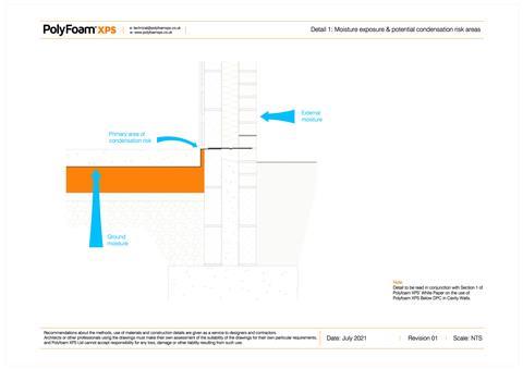
Technical guidance supporting Requirement C2 is provided in Approved Document C (England). Wales currently follows equivalent requirements and guidance, while Scotland sets out similar principles within Section 3 – Environment – of its Building Standards. This module focuses on the provisions applicable in England.
Floors and continuity of damp protection
Approved Document C provides detailed guidance on how ground-supported and suspended floors can resist moisture ingress. For solid floors, typically comprising a concrete slab, a DPM is an essential component. This membrane may be positioned either above or below the slab, depending on the construction approach.
A key principle is continuity of protection. The DPM must link effectively with the DPC in the surrounding walls to form a continuous barrier against ground moisture. Failure to achieve this continuity can create pathways for moisture ingress at junctions, undermining both durability and internal environmental conditions.
While suspended floors may not always require a DPM in the same way, their design must still ensure adequate resistance to moisture, particularly where ground conditions or ventilation strategies introduce additional risk.
External walls below DPC level
Guidance on the moisture performance of external walls is set out in Section 5 of Approved Document C. To resist moisture rising from the ground, walls must incorporate a DPC that is continuous with the floor DPM. This DPC should be positioned at least 150mm above adjacent external ground level to reduce the risk of splashback and capillary uptake.
For masonry cavity walls, additional provisions apply below DPC level. The cavity should either:
- Extend at least 225mm below the DPC, or
- Incorporate a cavity tray to intercept moisture and direct it safely outwards via weep holes.
These measures are intended to prevent moisture from crossing the cavity and reaching the inner leaf of the wall.
Managing moisture from outside
Approved Document C also addresses the control of precipitation in cavity wall construction. The outer leaf must be constructed from materials appropriate to the site’s exposure conditions, while maintaining a clear cavity width sufficient to limit moisture transfer across the wall.
The guidance also recognises that certain components may bridge the cavity, including wall ties and insulation materials. Where insulation is installed within the cavity, it must be suitable for the intended exposure conditions and application. In practice, this suitability is typically demonstrated through independent third-party certification, such as an Agrément certificate issued by the British Board of Agrément (BBA) or an equivalent body.
This requirement for demonstrated performance is particularly relevant when considering materials used in less common applications – such as insulation installed below DPC level – where standard certifications may not always directly apply. In these cases, compliance relies on a clear understanding of both regulatory intent and material behaviour.
Established approaches to cavity wall detailing
Standard masonry cavity wall constructions have evolved to provide a robust response to both moisture ingress and thermal performance, particularly at the critical wall-to-floor junction.
In conventional cavity wall construction, insulation is often designed to continue down within the cavity past DPC level, maintaining thermal continuity at the junction. This can be achieved through either partial fill or full fill approaches, depending on the overall wall specification and exposure conditions.
The following figures illustrate common approaches:
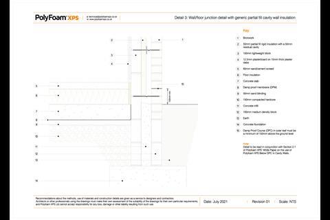
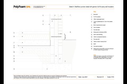
While the specific build-up may vary, these arrangements are widely used across residential and non-residential construction and form the basis of many compliant details.
Alignment with regulatory guidance
The detailing strategies illustrated above are consistent with the principles set out in Approved Document C. In each case, compliance is achieved by ensuring that:
- The DPM in the floor is continuous with the damp-proof course (DPC) in the wall.
- The DPC is positioned at least 150mm above external ground level.
Where partial fill insulation is used, the residual cavity typically extends at least 225mm below the DPC, helping to manage moisture movement within the wall. The required clear cavity width will depend on the site’s exposure to wind-driven rain, as defined in Approved Document C.
Across both partial and full fill solutions, insulation materials used within the cavity must be appropriate for the application. This is generally demonstrated through independent third-party certification, which verifies that the product performs as intended in relation to moisture resistance and durability.
At first glance, it may appear that third-party certification applies uniformly to insulation wherever it is positioned within the cavity. However, Approved Document C distinguishes between different zones of the wall, each with its own performance priorities.
Above DPC level, the primary concern is resistance to external moisture, particularly precipitation. It is in this context that the guidance explicitly refers to the use of insulation materials supported by current certification from an appropriate body, such as an Agrément certificate.
Below DPC level, the focus shifts to resisting moisture from the ground. While the same wall construction often continues through this zone, the regulatory emphasis is different, and the guidance does not prescribe certification in the same way. This does not remove the requirement to demonstrate suitability. Rather, below DPC level, compliance should be demonstrated against the relevant requirements of the Building Regulations through appropriate detailing, material performance and project-specific assessment.
This distinction is central to the growing interest in alternative approaches at the base of the wall. In particular, it has prompted designers to consider whether materials with inherent moisture-resistance characteristics may offer advantages below DPC level, even where their certification relates primarily to above-ground applications.
Rethinking insulation below DPC level
Having established how conventional cavity wall details meet regulatory requirements, this section considers how XPS insulation can be introduced below DPC level to respond to ground moisture conditions and improve junction performance.
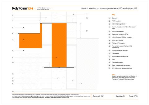
When used in conjunction with a typical above-DPC insulation such as polyisocyanurate (PIR) or phenolic foam, XPS can be installed within the cavity below DPC level in either a partial fill or full fill arrangement.
Where XPS is used as a partial fill, the residual cavity width should be maintained consistently with the construction above DPC level. This ensures that moisture management principles – particularly the provision of a clear cavity – remain unchanged through the wall build-up.
Where the cavity is fully filled below DPC level, a cavity tray must be introduced above the insulation to intercept and safely discharge any moisture. This reflects the requirement set out in Approved Document C for managing moisture within cavity walls where the cavity is bridged.
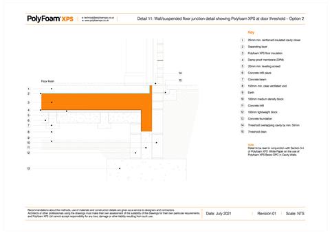
The introduction of insulation below DPC level has implications for key junctions, particularly at ground floors and around openings. The following figures illustrate typical approaches.
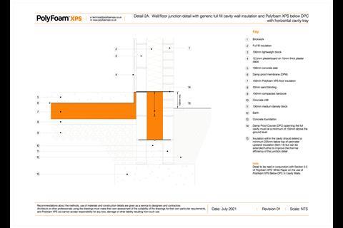
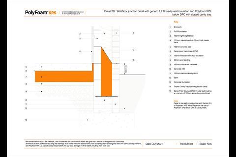
These details demonstrate how continuity of insulation can be achieved at the wall-to-floor junction while maintaining appropriate damp protection.
For suspended floors, attention is required around ventilation points. Historic guidance has highlighted that insulation is often omitted in these areas, particularly around telescopic vents, creating localised thermal bridges. Introducing insulation below DPC level can help address this, as shown below.
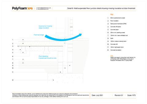
Similarly, door thresholds represent another area where insulation is frequently interrupted, increasing the risk of heat loss and surface condensation. Extending insulation below DPC level can improve thermal continuity at these junctions.
When incorporating insulation within the cavity below DPC level, several practical principles should be followed:
- Maintaining continuity of insulation to reduce thermal bridging at junctions
- Ensuring appropriate moisture management through the use of cavity trays where the cavity is fully filled
- Extending insulation sufficiently below DPC level to support both thermal and moisture performance at the junction
- Co-ordinating installation with wall ties, floor insulation and perimeter upstand insulation to ensure buildability.
These considerations are not prescriptive but reflect common approaches to achieving robust junction performance.
Thermal performance at the wall-to-floor junction
The below-DPC zone of a cavity wall is not only important from a moisture management perspective; it also forms part of one of the most influential junctions in the building envelope – the connection between the external wall and ground floor.
Poorly designed junctions can create thermal bridges, where heat flows more readily through the building fabric than in surrounding areas. This can reduce overall energy performance and create areas of lower internal surface temperature, increasing the potential risk of surface condensation and mould growth.
Building regulations require designers to consider heat loss through junctions as part of the overall energy performance strategy. Linear thermal transmittance (psi-value) is used to quantify heat loss through linear thermal bridges such as the wall-to-floor junction.
These values contribute to Standard Assessment Procedure (SAP) calculations, which are used to demonstrate compliance with energy efficiency requirements for dwellings.
A well-designed junction aims to maintain continuity of insulation between the wall and floor, reducing heat flow through the junction and helping to maintain a more consistent internal surface temperature.
Managing surface condensation risk
Thermal bridging also has implications for condensation risk. Where insulation is interrupted or insufficiently detailed, the internal surface temperature at the junction can fall significantly below that of the surrounding wall. If this temperature falls below the dew point, moisture from internal air can condense on the surface.
Approved Document C provides guidance on limiting condensation risk, including the need to consider junction details and ensure appropriate thermal performance of building elements. Approved Document L also requires reasonable provision to limit heat loss through thermal bridging and encourages the use of robust construction details supported by appropriate calculations or evidence.
Industry guidance, including the NHBC Technical Standards, similarly highlights the importance of maintaining continuity between wall and floor insulation to achieve consistent thermal performance and minimise risks associated with thermal bridging.
Assessing junction performance
To evaluate the potential impact of the below-DPC insulation approaches discussed, thermal modelling can be used to assess junction performance. This includes calculating psi-values and surface temperature factors.
A surface temperature factor (f-value) is used to assess the likelihood of surface condensation occurring. As a general benchmark, an f-value of 0.75 or above is commonly used to indicate an acceptable level of performance for avoiding surface condensation risk in dwellings.
For comparison, the default linear thermal bridging value used within SAP calculations is 0.32W/m·K. Junction details achieving lower values may provide an improvement over this default assumption.
The results demonstrate the potential thermal benefits of maintaining insulation continuity below DPC level. However, thermal modelling should always be considered alongside the specific wall, floor and insulation specifications proposed for an individual project. Project-specific calculations remain essential when demonstrating compliance.
Final thoughts
The junction between the external wall and ground floor requires careful co-ordination of moisture protection, thermal performance and buildability. As this module has explored, the area below DPC level plays an important role in achieving a robust building envelope, particularly where insulation continuity and resistance to ground moisture must be considered together.
While this module has examined typical approaches and the principles behind their performance, the details shown should not be treated as a substitute for project-specific design. Final specifications should be developed by the relevant design team, supported by appropriate calculations and assessment of the individual building conditions.
Where a below-DPC cavity wall solution is being considered, early consultation with building control bodies, warranty providers and other relevant stakeholders can help ensure that the proposed approach meets the necessary performance requirements.
Building regulations, standards and industry guidance continue to evolve. Designers should therefore ensure they are working from the latest available guidance and that construction details remain appropriate for the intended application.
The use of XPS insulation below DPC level represents one approach to addressing these challenges, with its moisture resistance and thermal characteristics making it a material option for consideration in this location. However, as with any construction detail, the suitability of a solution depends on the overall wall build-up, site conditions and project requirements.
Please fill out the form below to complete the module and receive your certificate.