


This CPD, sponsored by Farrat, will examine applications, options for structural thermal breaks, energy transfer and loss, materials, BRE analysis, thermal and structural performance and fire assessment.

CPD CREDITS: 60 MINUTES
For more information about Assemble Media Group’s CPD distance-learning programme, click here

![]()
Introduction
In construction thermal breaks prevent or reduce the flow of thermal energy between elements of a building. Structural thermal breaks help prevent thermal bridges in structurally loaded building details that pass between spaces of differential temperature. The two primary reasons for avoiding thermal bridges are to reduce energy loss and mitigate risk of condensation. The choice of thermal break material can significantly effect a buildings overall performance.
This CPD will examine applications, options for structural thermal breaks, energy transfer and loss, materials, BRE analysis, thermal and structural performance and fire assessment.
Why use thermal breaks?
Modern building design and regulation recognise the importance of energy conservation and occupier comfort in all aspects of construction detailing. Developments in material science and advanced manufacturing techniques have led to the use of structural thermal breaks. Structural thermal breaks are a solution to avoid thermal bridges in building details that pass between spaces of differential temperature, specifically where the thermal break material needs to perform both in transmitting structural loads as well as preventing thermal movement across the connection.
The impact of poor detailing resulting in thermal bridges occurring in building envelopes is well documented. The resultant energy loss can impact severely on the overall performance of a building in respect of the amount of energy required to heat or cool a space and the cost of that energy both monetarily and environmentally. Building regulations typically guide the designer in understanding the minimum requirements in thermal performance of building elements to achieve satisfactory thermal performance in respect of energy loss or gain. In England and Wales, approved Document L gives detailed guidelines for calculating Target Emissions Rates and Target Fabric Energy Efficiency and minimum values to satisfy these requirements.
Alongside energy loss, thermal bridges in a building fabric can result in condensation and mould growth. This is where the temperature of a room’s internal surfaces is sufficiently low for moisture laden air to reach a dew point temperature and condensate and, in some cases, for the propagation of mould spores to occur.
Applications
Structural thermal breaks can be incorporated into any detail where there is a calculated or perceived risk of a thermal bridge occurring. This is typically in details that occur in building envelopes or where significant temperature difference is likely to occur between compartments, such as highly controlled atmospheric environments (plant or server rooms) or warm high humidity environments, such a breweries or swimming pools.
Examples are:
- Façade system connections to the primary frame
- Brise Solei and canopies
- Roof plant room columns
- Balustrading
- External balconies
- External Staircases
- Man-safe systems
- Sub-structure and basement structure elements
- External to internal primary building element connections
The two principal types of structural thermal breaks are:
- ‘Mechanical’ – comprising of combinations of structural components and compressive insulating materials used to compensate for the poor thermal performance of the continuous steel elements
- ‘Solid State Thermal Break Plates’ – used in conventional connections as a structural ‘spacer’ that also has a high thermal performance.
Energy loss
All materials have a thermal conductivity value. The majority of materials with high structural properties have poor thermal conductivity, so these materials have to be supplemented or isolated with better performing materials in order to achieve an overall satisfactory thermal performance. In order to assess the relative thermal performance of combinations of materials in details empirical calculations can be carried out using the respective conductivity values and figures for the climactic environments into which they are due to be installed.
The simplest of these calculations is for plane elements which are expressed as a ‘U’ value. More complex to calculate are linear details which are expressed as a ‘Psi’ value, while the most complex to calculate are localised elements/point connections, which are expressed as a ‘Chi’ value. This last value is only able to be attained from complex three-dimensional modelling and is typically where the need for structural thermal breaks is required.
| Steel | 50.0 W/m-k |
| Stainless Steel | 43.0 W/m-k |
| Concrete | 2.1 W/m-k |
| Farrat TBL | 0.292 W/m-k |
| Wood | 0.22 W/m-k |
| Farrat TBK | 0.187 W/m-k |
| Soft wall insulation | 0.02 W/m-k |
Heat Loss is quantified using three parameters:
- Plane elements U value (W/m²K) [eg. floors, walls, windows]
- Linear elements ψ value (W/mK) [eg. Interface window/wall opening]
- Localised elements χ value (W/K) [eg. structural element penetrating through wall]
Condensation
Once a value for thermal transmittance through a detail is established this can be used to evaluate likely performance in relation to a critical temperature factor. These factors relate to a range of building types and the propensity for moisture to be present in the internal spaces.
The higher the likelihood of there being moist air present, the higher the likelihood of moisture condensing out and causing problems. As such, the higher the risk of condensation the more important it is to have sound thermal performance of the building fabric to avoid problems associated with condensation, such as mould growth or corrosion, both internally and within the building structure itself.
CE marking
There is no harmonised European standard for structural thermal breaks; consequently it is not possible to obtain a CE marked thermal break product. In view of the current position on CE marking the primary driver for having independent appropriate accreditation is to ensure that design teams and clients can have confidence in a product used in structural connections.
Materials testing
The provision of manufacturing standards allows specifiers to compare performance of differing materials as well as warranting product performance via independent testing. As with all construction products physical properties and levels of performance can be verified by testing against relevant standards for specific product groups. As new products are developed, standards are created to assess them. In the case of solid state structural thermal break plates there are currently no specific standards, therefore it is crucial that with these critical components independent verification of figures and performance is sought via accreditations such as BBA certification.
Material testing takes many forms and is in many cases tailored towards a specific end use. Where there are multiple ways of testing similar physical properties it is important that the right test is carried out to suit the situation in which the material is used. To this end material properties that can vary depending on variable use factors – such as compressive strength and thermal transmittance in relation to temperature – need to be assessed correctly. Materials which appear to have similar values can ultimately perform very differently in real life conditions.
| Properties | Farrat TBK | Farrat TBL | Units | Test Standard |
|---|---|---|---|---|
|
Compressive strength |
321.8 |
97.4 |
N/mm2 |
EN 826 |
|
Elastic modulus |
5178 |
2586 |
N/mm2 |
EN 826 |
|
Thermal conductivity |
0.187 |
0.292 |
W/mK |
EN 12667 |
|
Density |
1465 |
1137 |
Kg/m3 |
EN 12087 |
|
Water absorption |
0.14 |
0.48 |
% |
EN 12087 |
Carried out by an approved Nando Accreditation Facility.
| Test | Farrat TBK (N/mm2) | Farrat TBL (N/mm2) |
|---|---|---|
|
1 |
318.3 |
89.1 |
|
2 |
323.7 |
97.4 |
|
3 |
320.8 |
99.0 |
|
4 |
330.7 |
98.6 |
|
5 |
320.7 |
100.2 |
|
6 |
316.9 |
99.8 |
|
Mean |
321.8 |
97.4 |
|
Standard deviation |
4.50 |
3.80 |
The characteristic compressive strength values of Farrat TBK and Farrat TBL have been calculated in accordance with BS EN 1990, Annex D. The design resistance is calculated using Equation 1, which is based on BS EN 1990, Equation (D.1).
| Properties | Farrat TBK (N/mm2) | Farrat TBL (N/mm2) |
|---|---|---|
|
Characteristic compressive strength, fck |
312 |
89.1 |
|
Design value for compressive strength, fcd |
250 |
71.3 |
The characteristic values for design to BS EN 1993-1-8 should be converted to design values by using the partial safety factor gM2, which is defined as 1.25 in the UK National Annex.
Design – thermal performance
Finite Element Analysis is still currently the only way to empirically establish the performance of an elemental point connection. However this is a time-consuming and complicated process which is infrequently used to assess details. There are few standard construction details between projects, so detailing of the building envelope and penetrations can vary significantly. As a result, the calculation of thermal performance and compliance can be complex.
There are two aspects to the thermal performance of the building envelope; heat loss and condensation risk. Both issues are covered by Building Regulations and guidance on meeting them is provided in various Approved Documents (England and Wales), Technical Handbooks (Scotland) or Technical Booklets (Northern Ireland).
These documents currently require heat loss and condensation risk to be assessed in accordance with the same British Standards, European Standards and Building Research Establishment (BRE) publications. Unlike proprietary mechanical thermal break systems, Farrat structural thermal break plates are very simple to incorporate into most details. This flexibility means that it can be used for a wider variety of applications and is not restricted by the modular nature or the space required for proprietary mechanical systems. It also provides the designer with greater freedom to develop a bespoke solution.
Finite Element Analysis thermal modelling not only considers the direct connection of materials, but also the significant elements surrounding the connection. These surrounding elements have such an impact on the final result that they cannot be ignored in a simple calculation.
Building Research Establishment analysis
In the absence of a full thermal model of the actual detail being used, typical details can be modelled and used as indicators of likely performance and used to specify materials that will meet design requirements.
The BRE has produced indicative details available online to assist in the specification of Solid State Thermal Breaks, which can be relied upon in the absence of a full 3D model analysis.
Farrat is a member of BRE’s Certified Thermal Details and Product Scheme. The scheme database includes for both BRE Certified Thermal Details and Products and Government Accredited Details and this provides a freely accessible and independently assessed and certified resource for users. The third-party BRE global certification can distinguish products and services from their competitors and give customers confidence about the thermal performance of the products. The database has been developed to enable details to be linked directly into SAP 2016 and is also featured within the BRE Home Quality Mark standard.
A number of typical connection details have been analysed under the scheme to assist designers when specific modelling of their details is not undertaken. All details assessed (Ref 600063 to 600068) had a temperature factor above 0.80, meaning mitigation against risk of surface condensation. This includes:
- storage buildings
- offices
- retail premises
- dwellings
- residential buildings
- schools and sports halls
- kitchens and canteens
The ‘small beam’ steel to steel connection (Ref 600063) had a critical temperature factor above 0.90, meaning that in addition to the above there is also no risk of surface condensation for:
- swimming pools
- laundries
- breweries
After determining the thermal performance of the construction detail, either through modelling or using exemplar details for the smallest cross-sectional area of penetration/connection, the thickest thermal break plate able to be accommodated with the lowest thermal conductivity must be selected to ensure optimum performance.
Recommendations:
Carry out a full analysis of the cold bridge – heat loss/condensation risk in conjunction with codified methodology to determine the Thermal Break requirements.
The best thermal performance will be obtained by:
- developing the smallest cross-sectional area of penetration/ end connections
- using the smallest cross-sectional area of bolts through the connection
- use the thickest thermal break plate
- use materials with a low thermal conductivity value, k
- locate the thermal break connection within the insulated layer of the building façade/roof construction
Structural Design Summary (steel connections)
Connections that include thermal break plates should be designed in accordance with the relevant design standards (e.g. BS EN 1993-1-8) or industry guidance (e.g. SCI publications).
The following additional checks should also be undertaken:
- the thermal break plate can resist the applied compression forces.
- any additional rotation due to the compression of the thermal break plate (including allowance for long term creep) is acceptable.
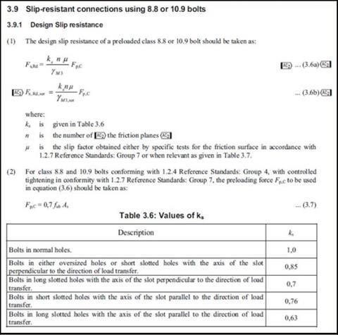
- the shear resistance of the bolts is acceptable given that there may be a reduction in resistance due to:
- • Packs – Clause 6.3.2.2 of BS 5950-1 or clause 3.6.1(12) of BS EN 1993-1-8
- • Large grip lengths – Clause 6.3.2.3 of BS 5950-1 or BS EN 1993-1-8
For connections involving concrete and masonry, the material principles detailed above should be considered in conjunction with the relevant Eurocodes. All connections involving proprietary fixing systems (non-standard) may require consultation with the product supplier.
This is the check list for thermal breaks that require a HSFG bolt. This is predominantly a requirement in the US or UAE following US design principles, but becoming more relevant in buildings with external skeleton structures.
Design – structural performance
As with all construction components, correct handling and installation are a critical part of the performance. Attention should be paid to any specific manufacturers requirements for handling; this should also include connection specific labelling, material conformity certification and batch traceability to ensure avoidance of site and design validation issues.
As well as the simple evaluation of a compressive strength figure, account should also be taken of the material’s ability to disperse loads from highly loaded points of a connection. This factor and a selected material’s ability to deal with these loads should be addressed by the material manufacturer.
All material-to-material connections have the potential to rotate under load. Note that care should always be taken to a) ensure that the chosen structural thermal break can resist these loads and b) to avoid compromising the short and long performance of a connection with undue flexibility or excessive creep.
Structural thermal breaks typically limit the extent of their load transmittance for design purposes to the transferal of compression loads. The main connection elements typically deal with shear loads. Notice should be taken of the effective connection lengths in relation to the thickness of structural thermal break specified. A thickness of 25mm would typically be the optimum without having to consider increasing the size of the bolt.
Design – fire performance
In the majority of applications there are no requirements to meet any fire regulations (outside the fire compartmentation). High rise buildings (over 18m/six storeys) now have stricter requirements for building envelopes following the Grenfell fire. Structural thermal breaks are excluded from the new Document B requirements but are a key component in high rise building facades.
Structural thermal breaks, like most building materials, can be produced with different grades of flammability and performance under fire loading. Where fire sits high up the order of risk, alongside structural and thermal performance, designers should look to choose a certified fire-resistant material.
The decision on specification of structural thermal breaks, by nature of their dual role, can come from a number of sources. It is crucial that the essential criteria for performance are understood by all parties and that the final product supplied is correct by specifically naming manufactures by name and product.
Generally, thermal breaks are used in locations that do not require fire protection. Where the connection requires a fire rating then the following options are available:
- A board fire protection system can be applied
- Sprayed fire protection can be applied. The compatibility of the applied fire protection material should be checked with the thermal break material
- The connection may be designed on the assumption of complete loss of the thermal break material in the accidental condition. For accidental conditions excessive deformations are acceptable provided that the stability of the structure is maintained.
Rules for fire protection are formulated in relation to time and the safety afforded to persons exiting the building and firefighters attending the blaze. A large part of this is the propensity of materials used to either contribute to the fire load and ease of ignition or continue to burn, causing the fire to spread.

How to take this module
Assemble Media Group’s CPD distance-learning programme is open to anyone seeking to develop their knowledge and skills. Each module also offers members of professional institutions an opportunity to earn between 30 and 90 minutes of credits towards their annual CPD requirement.
This article is accredited by the CPD Certification Service. To earn CPD credits, read the article and then click the link below to complete your details and answer the questions. You will receive your results instantly, and if all the questions are correctly answered, you will be able to download your CPD certificate straight away.
CPD CREDITS: 60 MINUTES
Privacy policy
Information you supply to Assemble Media Group Limited may be used for publication and also to provide you with information about our products or services in the form of direct marketing by email, telephone, fax or post. Information may also be made available to third parties. Assemble Media Group Limited may send updates about Building CPD and other relevant Assemble Media Group Limited products and services. By providing your email address you consent to being contact by email, telephone, fax or post by Assemble Media Group Limited or other third parties. If at any time you no longer wish to receive anything from Assemble Media Group Limited or to have your data made available to third parties, contact the Data Protection Coordinator at building@building.co.uk. View our full privacy policy her


No comments yet