


Levels of detail define the content of a BIM project at different stages. This CPD, sponsored by Vectorworks, outlines the main points to consider

How to take this module
UBM’s CPD distance-learning programme is open to anyone seeking to develop their knowledge and skills. Each module also offers members of professional institutions an opportunity to earn between 30 and 90 minutes of credits towards their annual CPD requirement.
This article is accredited by the CPD Certification Service. To earn CPD credits, read the article and then click the link below to complete your details and answer the questions. You will receive your results instantly, and if all the questions are correctly answered, you will be able to download your CPD certificate straight away.
CPD CREDITS: 60 MINUTES
DEADLINE: 5 MAY 2017

INTRODUCTION
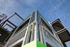
The Cube is a hypothetical building project in the heart of London, created by BIM software provider Vectorworks to demonstrate the workflows and practices within Level 2 BIM. A key objective of this project was to highlight the benefits of an organised workflow and show that it can empower rather than restrict the creative process. To allow project participants to focus on the underlying principles, they chose a minimal cube form on a 16m by 16m site and a stripped-down aesthetic.
The Cube is the subject of a CPD-accredited Building webinar in association with Vectorworks, entitled BIM: Are you moving to a 3D workflow? It is available for on-demand listening at www.building.co.uk/webinars.
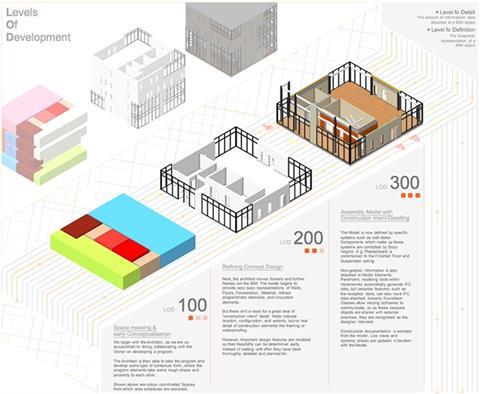
This complementary CPD article will focus particularly on one aspect of a 3D workflow: levels of detail, also referred to as levels of development (both abbreviated to LOD).
WHAT DOES “LOD” MEAN?
LOD defines the content of a BIM project at different stages in its development and refers to two elements: the geometry or visual representation of a project, and the attached data. It is the attached data that creates intelligent objects, and sets BIM modelling apart from dumb extrusions or polygons. The geometry and the data can be combined and exported as an IFC object or model. IFC refers to Industry Foundation Classes, the standard for sharing BIM data across different applications. This means that any professional that receives the object or model will not only be able to visualise the geometries, but also to understand the information attached.
The term “levels of development” was publicised by the American Institute of Architects in AIA E202-2008: Building Information Modelling Protocol Exhibit, published in 2008.
In the UK, the Construction Industry Council (CIC) first published a BIM protocol in 2013 in response to the government construction strategy, which set the deadline for Level 2 BIM compliance for publicly funded projects by 2016. The requirements of level 2 BIM have been covered in previous CPD modules, such as this one [http://www.building.co.uk/professional/cpd/cpd-6-2015-essential-bim-technology/5073872.article].
The CIC BIM Protocol defines the responsibilities, liabilities and limitations of project team members, and the deliverables at key stages in the process to a specific “level of detail”. This is also abbreviated to LOD and the stages are essentially analogous to the US definitions, although they are numbered differently. The UK definitions are contained in PAS 1192, the publicly available specification that sets out how information should be managed on BIM projects.
| UK LOD | US LOD | Description | Content |
| 1 | Brief | Block model with performance requirements, site constraints | |
| 2 | LOD 100 | Concept | Concept or massing model including basic areas and volumes, orientation and cost. In the RIBA Plan of Work, this is equivalent to stage 2 |
| 3 | LOD 200 | Developed design | Generalised systems with approximate quantities, size, shape, location and orientation. Equivalent to RIBA stage 3 |
| 4 | LOD 300 | Production | Technical design model, equivalent to RIBA stage 4. Accurate and coordinated modelled elements that can be used to estimate costs and check regulatory compliance. |
| 5 | LOD 400 | Installation | Model suitable for fabrication and assembly, with accurate requirements and specific components |
| 6 | LOD 500 | As constructed | Details of how the project has been constructed, for use in operations and maintenance |
| 7 | In use | Asset information model for operations, maintenance and ongoing monitoring |
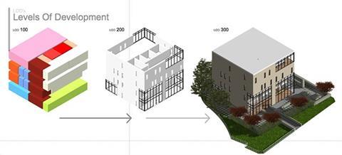
The Cube project, a hypothetical four-storey commercial project in the heart of London, comprised two phases – site development from imported shapefiles, and creating the building from a massing model and taking it through each of the design stages to produce the detailed construction model. First of all, Vectorworks software was used to create early massing studies (LOD 2 or 100). These were then refined to create concept walls, slabs etc (LOD 3 or 200), and then further refined to show construction intent (LOD 4 or 300).
The information generated at each stage was shared as COBie data drops. COBie stands for Construction Operations Building Information Exchange, a non-proprietary data format which is part of IFC. The data drops correlated with the Model Production and Delivery table, contained in Appendix 1 to the CIC BIM Protocol, which states what information has to be delivered at what point of development, and to whom.
EARLY MASSING STUDIES
All projects start with spaces: intelligent objects with data attached so that reports can be extracted from them at a very early stage. A space for stairs, for example, can be viewed immediately in both 2D and 3D, enabling the generation of a live and dynamic space report.
In addition to space information, assigned zones must also be included to meet the requirements of COBie. For example, are areas accessible by the public or are they private or secure spaces? Plant spaces can also be established here, and configured with building services requirements, in addition to more general information such as room dimensions and volumes.
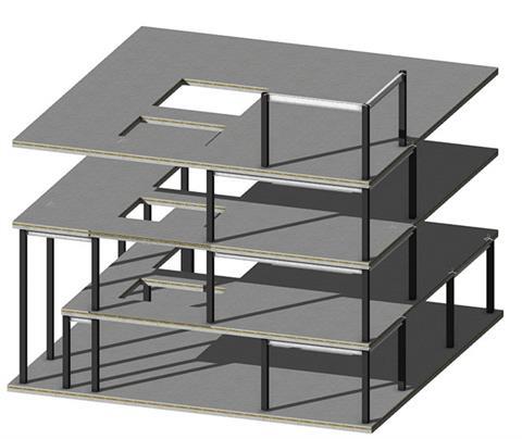
Organisation is key to taking the model forward. For example, concept walls are defined by “stories” in Vectorworks software, and may simply consist of a slab level, a finished floor level and a suspended ceiling level. At concept stage, the entire wall will snap to one of these levels, but as the model is further refined, components within the walls will need to snap to varying levels: so, exterior walls will run from one floor slab to the slab above, while interior walls will run only to suspended ceilings.
Classification is another important factor. Using Uniclass 2015, a universal classification system for the UK construction industry developed by NBS, walls can be classed as being merely internal or external, or classified in more depth, defining components within the wall and the classes
they fit into. Early stage wall location establishes its configuration and extent, but no information about construction intent has been supplied. We know how the walls fit at that point but not what they are made of.
On The Cube project, terrain survey data in the form of shapefiles was used initially to develop a highly detailed 3D model of the site in which to place the building, close to London’s Soho Square. The shapefiles describe vector features – lines, polygons, points – through attributes, and they will ultimately be incorporated within the model.
The first shapefile to be imported into the software consisted of 3D points, each endowed with latitude, longitude and altitude values expressed in millimetres. By selecting all the points, it was possible to create a site model, which translated the data into three-dimensional geometry. A further shapefile was imported, this time consisting of 3D polygons, representing the buildings, the roads and the natural elements of the site.
Within Vectorworks’ software, the vectors of a shapefile can be visualised, and the attributes that describe that geometry can also be retained. So, by clicking on any element, the software provides a huge set of data that changes according to the nature of the element itself – for example, the date of the survey, the type of element and its characteristics, whether it’s manmade or natural etc.
The “modify by record” tool was used to edit the polygons by applying colours to different categories, so that the buildings became easier to visualise from the context and to model subsequently. In order to do that, the team created a massing model, an intelligent parametric object that can be personalised using the “object info” palette. This model can also be created using the “create object from shape” tool by right-clicking on one of the polygons. The data contained within every massing model, such as the number of floors, usage, slab and roof thicknesses, can be shown within reports and schedules that are directly linked to the model.
Having designed the building, the next step was to create adjoining roads using the “custom roadway” tool. Its main properties allow controlling items like the kerb, its height, the road thickness and the general rise of the road. In Vectorworks Landmark software, the “hardscape” tool was used to create pavements within the model, which were eventually populated with street lamps, trees, cars, zebra crossings and other street furniture – all available within the Vectorworks libraries. Once the site model was finalised, any element could be inspected more closely using the Clip Cube live section tool.
ARCHITECTURAL DEVELOPMENT
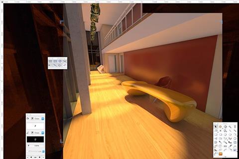
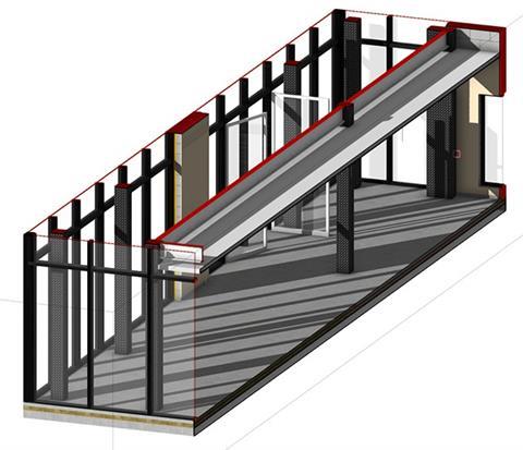
During this stage of the demonstration an auditorium space was configured with dedicated lighting. To understand circulation and other factors, the model was populated with furniture and other components, included within the software. Rows of seats were automatically placed by drawing a rectangle and using the “object info palette” to populate it with seats and then edit, offset or rearrange them in different formats. Other intelligent components included a wall-mounted video screen which, with a further click, instantly showed its coverage zone. With stage decking even at such an early point the team were able to produce a detailed rendered view of the furnished auditorium, using the built-in Cinema 4D render engine. At the end of LOD 3, therefore, with refined spaces and the depths and thicknesses of walls established and approved, it was possible to move on to developing construction intent detail.
Walls defined at concept design level could be selected and, using the “select similar” tool in Vectorworks 2016, replaced with preconfigured wall styles using intelligent wall-join tools, which understand junctions and complete walls automatically. With the “hide details” function, architects can hide details in plans that they may not wish to share with contractors. For part of the external walls, the “curtain wall” tool was used, which enables users to edit mullions, add slants to mullions and edit any other parameter within the curtain wall itself, or to select individual panels, covering stairs or suspended ceilings and blank them out.
ACHIEVING A LOD 4 MODEL
A frequent concern among architects is that every part of a building must be modelled when using BIM. However, this is not the case. At 1:50 or 1:100 scale you can copy the BIM section across, select the part that you want to highlight, zoom into it, crop it out, discard the cropped element and scale up the crop, showing model details. This can also be achieved using the “callout” tool. In the developed model, it is possible to isolate and display specific areas – the structural shell, for example – in order to focus on complex construction issues. This is possible because of the level of organisation, hopefully introduced early on in the model, in the form of design layers, stories and classes.
At the end of The Cube project, a full LOD 4 model had been produced: a fully integrated building with associated views, and with dynamic sections that will update automatically as the model is developed further. The space the building is located on was populated with landscape features and trees.
For presentations, Vectorworks 2016 also includes “white card” renders – sophisticated models that can be shown to the client. From the same design model, therefore, it is possible to create any 2D or isometric construction view and display it on sheets, with consistency of information throughout. Views can be shown as traditional or orthogonal, all editable within the “object info” palette. Vectorworks 2016 also enables architects to create a wide range of special views, including exploded views of stories and other details.
How to take this module
UBM’s CPD distance-learning programme is open to anyone seeking to develop their knowledge and skills. Each module also offers members of professional institutions an opportunity to earn between 30 and 90 minutes of credits towards their annual CPD requirement.
This article is accredited by the CPD Certification Service. To earn CPD credits, read the article and then click the link below to complete your details and answer the questions. You will receive your results instantly, and if all the questions are correctly answered, you will be able to download your CPD certificate straight away.
CPD CREDITS: 60 MINUTES
DEADLINE: 5 MAY 2017
Privacy policy
Information you supply to UBM Information Ltd may be used for publication and also to provide you with information about our products or services in the form of direct marketing by email, telephone, fax or post. Information may also be made available to third parties. UBM Information Ltd may send updates about Building CPD and other relevant UBM products and services. By providing your email address you consent to being contacted by email by UBM Information Ltd or other third parties. If at any time you no longer wish to receive anything from UBM Information Ltd or to have your data made available to third parties, contact the Data Protection Coordinator, UBM Information Ltd, FREEPOST LON 15637, Tonbridge, TN9 1BR, Freephone 0800 279 0357 or email ubmidpa@ubm.com. View our full privacy policy at www.building.co.uk/cpd


No comments yet