


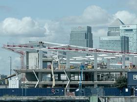
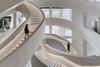
The Crystal, a dramatic urban sustainability centre built for Siemens in east London’s docklands, uses an innovative steel framework to enable its complex crystalline form
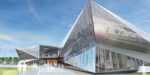
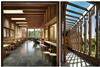
One side of the Crystal houses an exhibition space, the other contains offices for 250 Siemens staff.
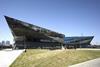
Originally known as the Siemens Urban Sustain- ability Centre, this £30 million building has been renamed the Crystal as the design of its eponymous faceted geometry has evolved. According to Siemens, the shape is intended to represent the many facets of sustainability and the complexity of urban life.
Designed by Wilkinson Eyre Architects, the building is located on the western edge of the Royal Victoria Dock in east London and is intended as a showcase for sustainable design for both businesses and the public.
The Crystal, which is nearing completion, will be Breeam Outstanding and LEED Platinum. Conceived as an exemplar project for sustainable construction, this structural steel-framed building includes high-performance glazing, PV panels and energy-efficient services including a ground-source heat pump. Grey and black water recycling is expected to reduce water demand by 90%. Designed to be all electric, the building will be able to operate free of fossil fuels. It will make use of a mixed mode ventilation strategy and, where seasonally possible, will be naturally ventilated in both the office and exhibition crystals, using opening vents in the facades and roofs.
The dynamic building form is driven by this sustainable agenda and incorporates two parallelogram “crystal” forms broken into a series of triangulated facets and linked by an internal street. Because the facets have varying orientations, they will reflect the light differently to create, according to the architect, a dynamic and reciprocal reflection of its waterside setting.
Each of the two crystal-shaped sections is supported by 14 tapering steel columns. The north side houses an exhibition space exploring best practice in urban planning and design. To the south are offices for 250 Siemens staff plus conference facilities including meeting rooms, a café, a restaurant and a 300-seat auditorium.
At either end of the triangular street are public and private entrances, the public one to the east nearest the dock. In the centre of the street is the main reception with views into the exhibition hall.
“No piece of glass or angle of steelwork is the same, which is a very interesting challenge,” says Sebastien Ricard, a director of Wilkinson Eyre.
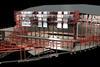
“While the facade appears to be made up of a set of random shapes, we created a rational geometry by defining the overall building form around two main parallelograms in plan with a very large span structure inside.
“Working with Arup, we designed a diagonal grid, a set of variable span portal frames. The columns/roof beams vary in height/depth and thickness in relation to their respective span in a parametric way, offering an optimised lightweight structure which ‘picks up’ all the key nodes defining the roof geometry.”
The lightweight facade structure of the exhibition section is self-supported from the roof to the floor and is cranked to follow the geometry of the main facets.
The main structural components are formed of bespoke steel mullions which are approximately 2m apart.
Located within London’s Green Enterprise District close to the new cable car and the Olympic Park, the Crystal is on course to complete ahead of the Olympics and will host the world’s largest exhibition focused on urban sustainability, which is expected to attract 100,000 visitors per year. The aim is that it will provide a global knowledge hub to help a diverse audience understand how to build better cities.
Roof structure

The complex irregular geometry of the building, with each column and beam a different height or span, led the design team to consider many options for the roof including fanning and spider web approaches before settling on a diagonal solution formed by seven portals.
The roof surface is in six planes with the outer one cantilevering out from the grid of columns by a maximum 15m.
The roof plate is carried by steel plate box girders, prefabricated and bolted together. These are shaped to match the stress demands so are deeper where necessary and stronger and shallower elsewhere to optimise the amount of steel plate used.
All the primary steelwork including columns and edge beams are fabricated box sections. Eighty-five per cent of the roof connections were welded in situ, including the 72m longest main rafters, which arrived in two pieces.
“One of the biggest problems was making connections work that would be aesthetically acceptable,” says Richard Cherrington, contracts manager of steelwork contractor Rowecord.
“We had to come up with some quite imaginative welding.”
Tapering columns
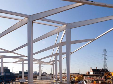
The most interesting and elegant part of the structural design is that of the tapering and twisting columns, according to structural engineer Chris Carroll, director of Arup.
The columns — 14 per crystal — are located in the points where the roof plane folds in order to maximise the column-free spaces, and range in height from 8-17m above slab level.
These are connected by roof girders to make a portal frame with spans ranging between the columns from 9m to the maximum span of 42m. However, they also act as cantilevers.
Wind loads
To provide sufficient wind load rigidity, the columns rotate through 90 degrees and taper towards the ground. By transforming in section over its height in this way, it is strong in one direction at the top (in the direction of the portals) and strong in the other direction at the bottom (to allow the columns to canti-lever from the base in this direction).
All have “collars” for the floor to slot neatly beneath.
“Our aim was to deliver something structurally elegant that minimised the amount of material and optimised construction time by prefabricating and modularising as much as possible, given that the geometry had inherent complexity,” says Carroll. “The structure was reacting to the design rather than driving it.”
Rainwater collection
Four of the corner node columns — two per crystal — have integral stainless-steel drainpipes that unobtrusively deliver water into the rainwater collection system and are cranked to follow the facade. This was achieved by cutting a section out of the hollow column section to insert the kinked 200m-diameter downpipe and then welding it all up again.
“All you see is a square hollow section column coming down but the amount of work that went into it was immense,” says Rowecord’s Richard Cherrington.
ISG senior project manager Mike Jenner said: “The design concept led to the decision to use structural steelwork. To achieve the project’s slenderness and get the detailing correct would have been extremely difficult with any other framing material.”
PROJECT TEAM
Client Siemens, Architect Wilkinson Eyre, Interior architect Pringle Brandon, Multi-disciplinary engineering Arup, Project management/cost consultant Turner & Townsend, Main contractor ISG, Steelwork contractor Rowecord Engineering
Postscript
In association with The British Constructional Steelwork Association and Tata Steel
![]()


No comments yet